
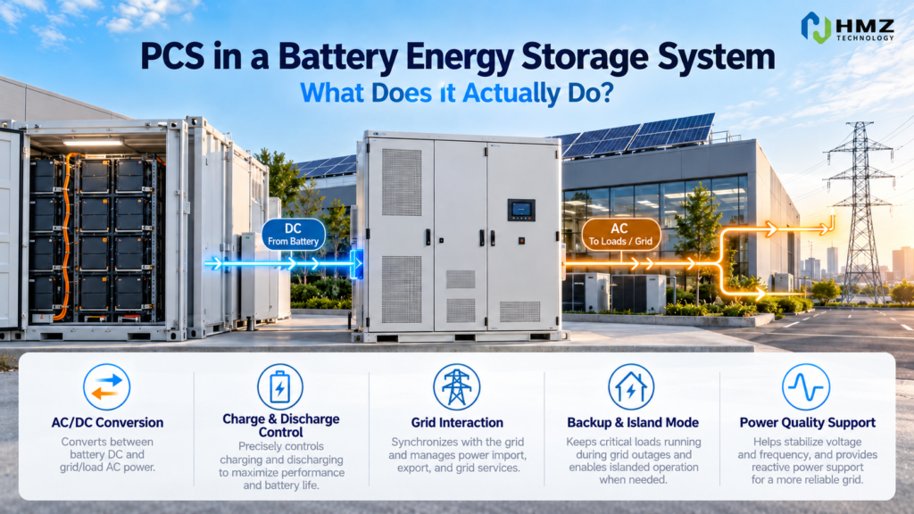
A battery stores energy in DC.
A factory, office building and utility grid usually operate on AC.
Something has to sit between those two electrical worlds.
That device is the PCS — Power Conversion System.
In a commercial BESS, the PCS does far more than simply “convert DC to AC.”
It determines how much power the battery can charge or discharge, how the system interacts with the grid, and whether certain backup or microgrid functions are possible.
This is why understanding PCS battery storage is important before comparing BESS specifications.
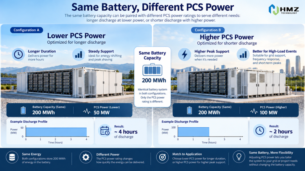
A 500 kWh battery with a 100 kW PCS behaves very differently from the same 500 kWh battery connected to a 250 kW PCS.
The stored energy may be the same.
The usable power is not.
What Is a PCS in Battery Storage?
PCS stands for Power Conversion System.
Its basic job is to manage electrical power between:
Battery DC side
and
AC electrical system
That AC system may be:
- a commercial facility,
- an industrial plant,
- a microgrid,
- or the public utility grid.
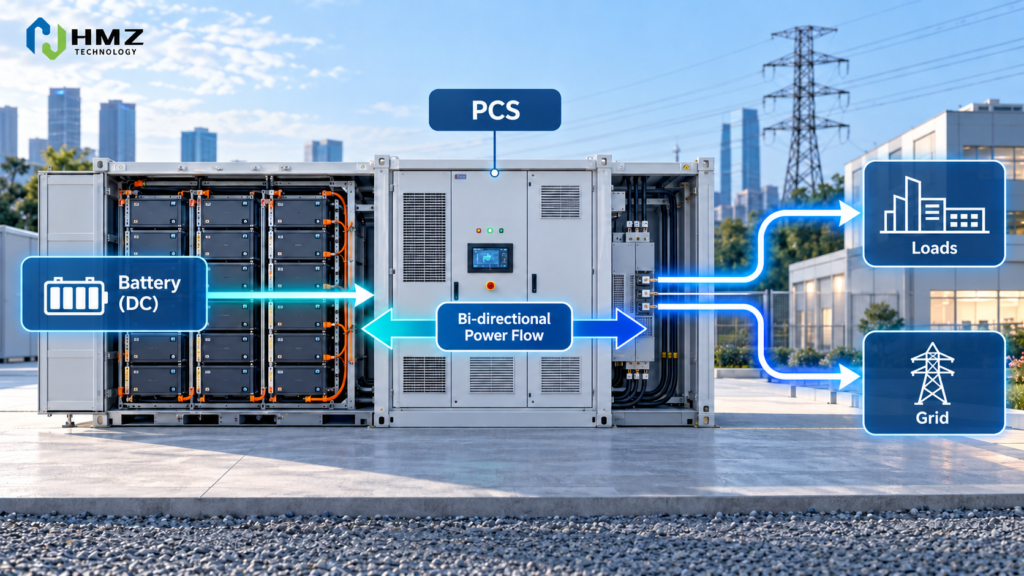
During charging:
AC → PCS → DC → Battery
During discharging:
Battery → DC → PCS → AC → Load / Grid
Because power flows in both directions, a BESS PCS is normally bidirectional.
That is one of the biggest differences between a simple solar inverter and a battery PCS.
Why the PCS Is Not the Same as the Battery
This sounds obvious, but it causes a lot of confusion in C&I storage quotations.
Customers may ask:
“How large is the battery?”
That question can mean two different things.
Battery Energy
Measured in:
kWh
This tells you how much energy can be stored.
PCS Power
Measured in:
kW
This tells you how quickly that energy can move in or out of the battery.
For example:
Battery energy:
500 kWh
PCS power:
100 kW
At full discharge power, the simplified duration is:
500 kWh ÷ 100 kW = 5 hours
Now use the same 500 kWh battery with:
250 kW PCS
Simplified duration at full power becomes:
2 hours
The battery energy did not change.
The power capability did.
For the basic relationship between these two values, see kW and kWh in commercial energy storage.
PCS Battery Storage Power Rating Determines Charge and Discharge Speed
The PCS places a practical power limit on the BESS.
Suppose a battery cabinet has:
261 kWh energy
but the PCS is rated:
125 kW
The system cannot normally discharge 261 kW simply because the battery contains 261 kWh.
Its AC power output is limited by the PCS and other system constraints.
This matters in applications such as:
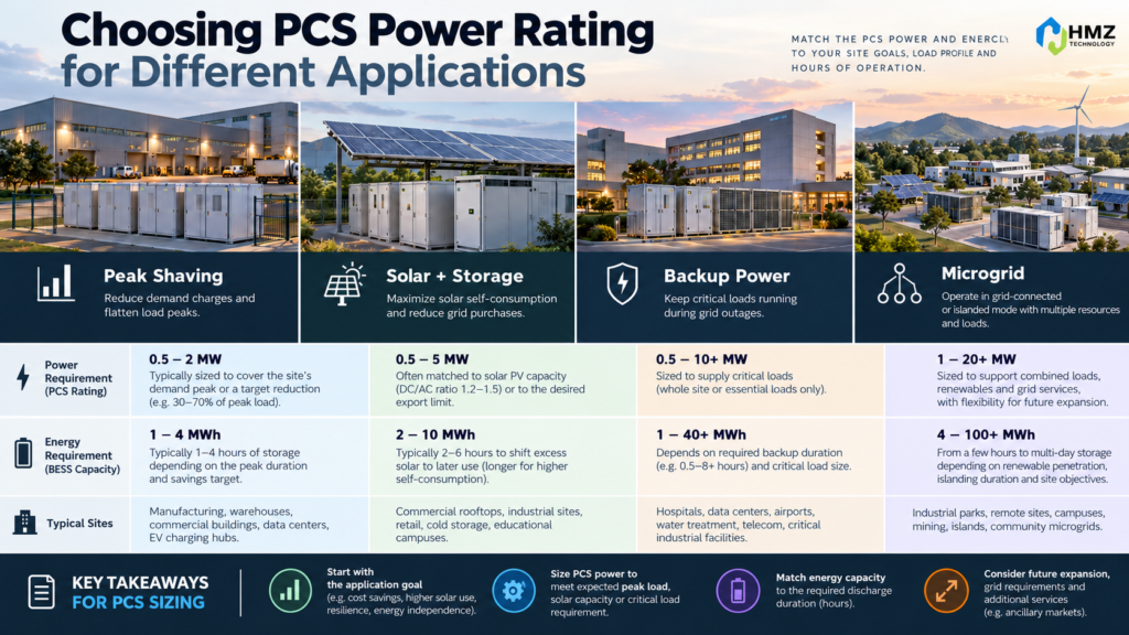
- peak shaving,
- backup,
- rapid charging,
- demand response,
- microgrid support.
If a factory needs to reduce a 200 kW demand peak, a 100 kW PCS cannot provide the full 200 kW reduction by itself.
Even if the battery contains plenty of energy.
How the PCS Controls Battery Charging
When the battery charges from the AC side, the PCS converts AC electricity into DC.
But it does not simply send unlimited power into the battery.
Charging is coordinated with:
- BMS limits,
- battery SOC,
- cell temperature,
- battery voltage,
- EMS commands,
- PCS rating.
Suppose the EMS requests:
100 kW charging
but the BMS reports that battery temperature or SOC requires lower charging power.
The final charging command may be reduced.
This illustrates an important relationship:
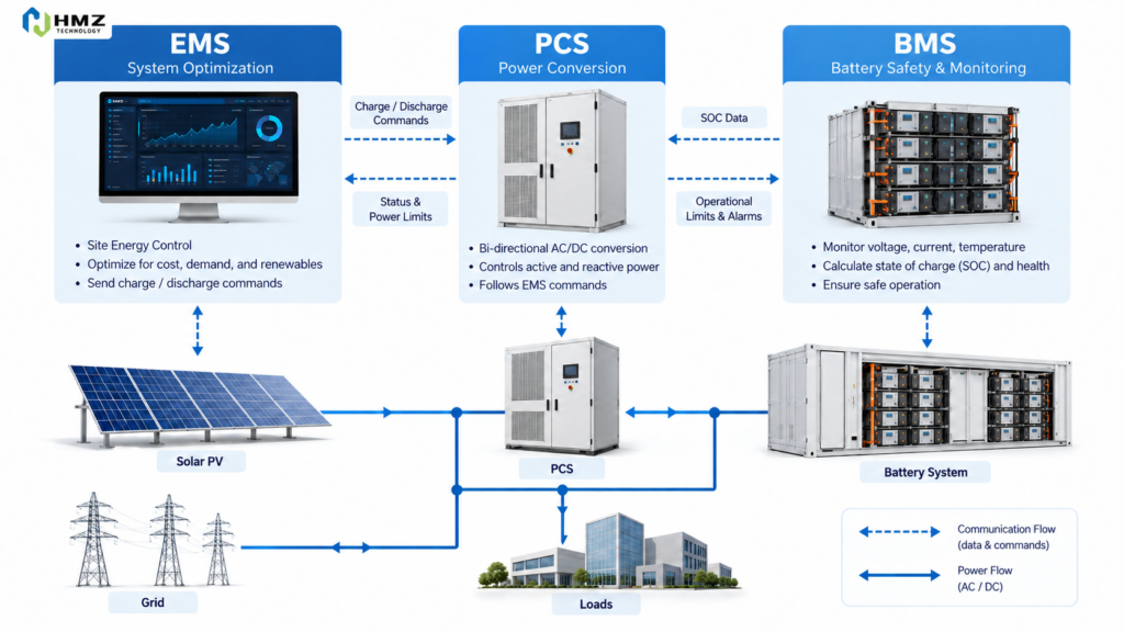
EMS decides what the system wants to do.
BMS protects what the battery is allowed to do.
PCS executes the power conversion.
We will explore these control layers separately in the next article on BMS vs EMS vs PCS.
How the PCS Controls Battery Discharging
During discharge, the process reverses.
The PCS converts battery DC power into AC power that can be used by the facility or exported where permitted.
The requested output may depend on:
- facility demand,
- peak-shaving target,
- electricity tariff,
- grid conditions,
- backup strategy,
- battery SOC.
For example, a facility may have:
Current load:
600 kW
Grid target:
500 kW
The EMS requests:
100 kW BESS discharge
The PCS converts and supplies approximately that required AC power, within its operating limits.
This is the power-conversion step behind peak shaving battery storage.
PCS Efficiency Matters
Power conversion is not perfectly lossless.
Every time electricity passes through the PCS, some energy is lost as heat.
For example:
Battery sends:
100 kWh DC
The AC side receives somewhat less than 100 kWh.
The exact efficiency depends on:
- PCS design,
- operating power,
- voltage,
- temperature,
- system conditions.
This is one reason BESS economic models should not assume that every kWh charged into the battery returns as one full kWh later.
PCS losses are one part of overall round-trip efficiency.
PCS Battery Storage and Peak Shaving
Peak shaving is mainly a power problem.
Suppose a factory wants to reduce grid demand from:
700 kW
to:
550 kW
Required battery contribution:
150 kW
If the BESS has:
125 kW PCS
then the system cannot fully provide a 150 kW reduction at one moment.
A larger battery energy capacity would not fix that issue.
The limitation is power.
The PCS rating needs to match the required peak reduction.
This is why BESS sizing should not start with kWh alone.
PCS Battery Storage and Backup Power
Backup applications make PCS capability even more important.
During normal grid-connected operation, the PCS can use the utility grid as an electrical reference.
When the grid fails, that reference disappears.
If the project requires island operation, the PCS may need to support local voltage and frequency.
This brings us to the difference between:
grid-following
and
grid-forming
operation.
Grid-Following PCS vs Grid-Forming PCS
These terms matter a lot in microgrid and backup projects.
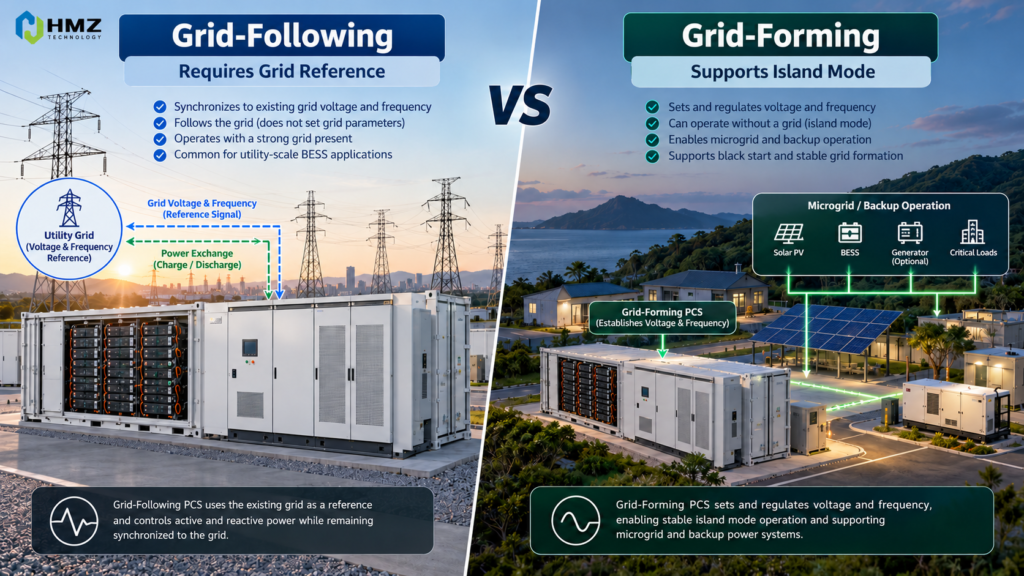
Grid-Following PCS
A grid-following PCS normally operates with an existing AC grid.
It synchronizes with the voltage and frequency already present.
In simple terms:
The grid exists first.
The PCS follows it.
Grid-Forming PCS
A grid-forming PCS can establish a local voltage and frequency reference.
That means it can help create the electrical foundation for an islanded microgrid.
In simple terms:
The utility grid disappears.
The PCS helps create the local grid.
This distinction is critical.
A BESS may work perfectly for grid-connected peak shaving but still be unsuitable for independent island operation if its PCS and controls do not support the required functionality.
What Happens to the PCS During a Grid Outage?
In a properly designed backup-capable system, a grid outage can trigger several steps.
1. Detect Grid Failure
Protection identifies abnormal grid conditions.
2. Isolate from Utility
Switching equipment disconnects the local system.
3. Change PCS Operating Mode
The PCS transitions according to the backup strategy.
4. Establish or Support Local Grid
If designed for grid-forming operation, the PCS regulates local voltage and frequency.
5. Supply Critical Loads
Battery power flows through the PCS into the local AC bus.
This is the electrical heart of commercial battery grid outage operation.
The PCS Also Has to Handle Transient Power
Steady-state power is not the only requirement.
Some commercial loads may require high short-duration power.
Examples include:
- motors,
- pumps,
- compressors,
- HVAC systems.
A motor may run normally at:
40 kW
but demand substantially more power during startup.
The battery may contain enough energy.
But if the PCS cannot provide the transient power, the equipment may fail to start.
This is why backup-system design needs to review:
- continuous PCS power,
- overload capability,
- transient response,
- startup loads.
The PCS specification should be matched to actual equipment behavior.
PCS and the BMS Must Work Together
The PCS controls electrical conversion.
The BMS protects the battery.
The BMS monitors parameters such as:
- cell voltage,
- module voltage,
- temperature,
- SOC,
- current,
- alarms.
If the PCS requests too much charging or discharging power, the BMS can restrict operation according to battery conditions.
A simplified relationship is:
EMS → sends operating target
BMS → confirms safe battery limits
PCS → converts the actual power
None of these systems works completely independently.
PCS and EMS Must Also Work Together
The EMS decides when the battery should charge or discharge according to the project’s operating objective.
For example:
Peak Shaving
EMS:
“Grid demand is approaching 500 kW.”
PCS:
Discharge 80 kW.
Solar Self-Consumption
EMS:
“PV surplus is available.”
PCS:
Charge battery at 100 kW.
Grid Outage
EMS:
“Utility unavailable. Enter backup strategy.”
PCS:
Support islanded AC bus according to configured mode.
The PCS is therefore the execution layer between energy-management decisions and real electrical power.
How the PCS Affects Solar + Storage Architecture
In commercial solar + storage systems, the PCS architecture depends partly on how the project is coupled.
In an AC-coupled retrofit:
Existing PV inverter:
PV DC → Solar Inverter → AC Bus
Battery system:
Battery DC ↔ PCS ↔ AC Bus
The existing solar inverter and battery PCS operate as separate power-conversion paths.
This architecture is common when battery storage is added to an existing commercial solar installation.
For the architecture comparison, see our DC-coupled vs AC-coupled solar + storage guide.
Does a Bigger PCS Always Mean a Better System?
No.
A larger PCS increases available power.
But it can also increase:
- equipment cost,
- electrical connection requirements,
- transformer requirements,
- cable size,
- protection requirements.
If a site only needs:
80 kW peak shaving
installing a much larger PCS may provide limited additional value unless there is another application.
The PCS should be sized around:
- load requirement,
- discharge requirement,
- charge requirement,
- backup power,
- transient demand,
- grid connection.
Bigger is useful only when the project can use the extra power.
This is the same principle behind avoiding battery oversizing.
A Practical PCS Sizing Example
Consider a commercial facility with:
Peak demand:
600 kW
Desired grid limit:
475 kW
Required peak-shaving power:
125 kW
The site also wants:
- solar self-consumption,
- two-hour peak support,
- limited backup.
A system with approximately:
125 kW PCS
and suitable battery energy may align well with the peak-shaving objective.
Now suppose the same site wants to support:
250 kW of critical loads
during an outage.
The 125 kW PCS would no longer be sufficient to supply all critical loads simultaneously.
The project must either:
- increase PCS power,
- reduce critical-load demand,
- use multiple units,
- or coordinate other power sources.
This is why the PCS cannot be selected from battery kWh alone.
PCS Power Also Affects Charge Time
Suppose the battery needs to receive:
400 kWh
of energy.
With a theoretical:
100 kW charging rate
minimum charging time is roughly:
4 hours
With:
200 kW
it may be closer to:
2 hours
before considering efficiency and battery limits.
This matters when:
- off-peak tariff windows are short,
- solar charging windows are limited,
- the battery must recover before the next peak,
- frequent cycling is required.
A PCS that is too small may prevent the battery from fully using the available charging opportunity.
What Should Buyers Check When Comparing PCS Specifications?
Do not compare only one kW number.
Useful points include:
Rated AC Power
Continuous output capability.
Maximum AC Power
If specified separately.
Overload Capability
Important for transient events.
AC Voltage
Must match project architecture.
DC Voltage Range
Must match the battery system.
Efficiency
Affects conversion losses.
Communication
Common interfaces may include:
- RS485,
- Ethernet,
- CAN,
- Modbus depending on system design.
Grid Support Functions
Depending on the project:
- reactive power,
- power-factor control,
- voltage support,
- frequency support.
Grid-Forming Capability
Required where island operation depends on the PCS forming the local electrical reference.
Specifications should always be checked against the actual model and project.
PCS Is One Part of the Complete BESS
A commercial battery storage system usually includes more than:
battery + PCS
Other important parts may include:
- battery modules,
- BMS,
- EMS,
- thermal management,
- fire protection,
- switchgear,
- protection,
- metering,
- communications.
Each layer has a different job.
The PCS controls power conversion.
It does not replace the BMS.
It does not replace the EMS.
It does not replace electrical protection.
That distinction makes BESS architecture much easier to understand.
How HMZ Technology Uses PCS in C&I Energy Storage
HMZ’s C&I energy storage portfolio includes different system configurations for commercial and industrial applications.
50kW / 112kWh All-in-One C&I ESS
A smaller power-to-energy configuration suitable for distributed commercial applications.
125kW / 241kWh All-in-One C&I ESS
Suitable for larger C&I loads and applications such as:
- peak shaving,
- solar + storage,
- energy management.
125kW / 261kWh Liquid-Cooled C&I ESS
Configured with built-in PCS and liquid cooling for higher-duty C&I applications.
Learn more about the 50kW/112kWh and 125kW/241kWh All-in-One C&I Energy Storage Systems.
For the liquid-cooled configuration, see the 125kW/261kWh Liquid-Cooled C&I Energy Storage System.
PCS Battery Storage Selection Checklist
Before confirming a PCS configuration, check:
Application
- peak shaving
- TOU shifting
- solar self-consumption
- backup
- microgrid
Power Requirement
- maximum charge kW
- maximum discharge kW
- critical-load kW
- transient load
Battery
- battery voltage
- DC operating range
- usable energy
- BMS compatibility
AC System
- grid voltage
- transformer
- switchgear
- point of connection
Backup
- grid-forming required?
- island mode required?
- transfer-time requirement?
- generator integration?
Control
- EMS communication
- BMS communication
- monitoring requirements
- dispatch strategy
The correct PCS is the one that matches the complete electrical system.
Conclusion
The PCS is one of the most important parts of a commercial BESS because it controls how battery energy becomes usable electrical power.
In PCS battery storage, the PCS determines:
- charging power,
- discharging power,
- AC/DC conversion,
- grid interaction,
- backup power capability,
- and potentially island-mode operation.
Battery kWh tells you how much energy is stored.
PCS kW tells you how quickly that energy can be used.
And PCS operating capability tells you what the system can actually do when conditions change.
So when comparing commercial battery systems, do not ask only:
“How many kWh is the battery?”
Also ask:
“What PCS is inside, how much power can it deliver, and what operating modes does it support?”
That question often tells you far more about how the BESS will behave in the real project.
Frequently Asked Questions
What does PCS mean in battery storage?
PCS stands for Power Conversion System. It converts electricity between the battery’s DC side and the AC electrical system.
Is a PCS the same as an inverter?
They are closely related, but a BESS PCS is typically a bidirectional power-conversion system designed for both battery charging and discharging and may include additional grid-control functions.
Why is PCS power measured in kW?
The PCS rating describes how much electrical power can be converted at a given time.
Does a larger battery require a larger PCS?
Not necessarily. PCS size should match the required charge, discharge, backup and operating power rather than battery energy capacity alone.
What is a grid-forming PCS?
A grid-forming PCS can establish and regulate local voltage and frequency, which can be important for islanded microgrid operation.
Can the PCS determine battery backup power?
Yes. Even if the battery has sufficient energy in kWh, the PCS must have enough power in kW to supply the required backup load.
Build Your Intelligent Energy Future with HMZ
HMZ Technology helps businesses move beyond traditional solar systems by combining solar PV, battery storage and intelligent microgrid control.
Our integrated energy solutions are designed for industrial facilities, commercial buildings and remote energy applications requiring reliable, efficient and flexible power.
Contact HMZ Technology today to explore your next solar storage or microgrid project.
Related Insights from HMZ Technology
Industrial energy management is rapidly evolving. While rooftop solar PV provides an effective way for factories to generate clean electricity, many businesses are now looking beyond solar generation and exploring integrated solutions such as energy storage, intelligent energy management, and microgrid systems.
To better understand how commercial and industrial users can optimize their energy strategy, explore more insights from HMZ Technology’s renewable energy knowledge center, including solar PV solutions, C&I energy storage systems, and practical applications for industrial energy management.